How to Choose the Right Solar Mounting Structure for Bifacial Panels to Maximize Rear-Side Generation?
Quick Answer / Expert Engineering Verdict: Deploying bifacial solar modules on traditional, low-profile racking systems can destroy up to 80% of their potential rear-side energy gain due to structural shading and poor ground clearance. To unlock the full 10%–20% bifacial boost, EPCs must utilize highly engineered racking designs featuring elevated ground clearance (minimum 1.0m to 1.5m), optimized purlin placement (avoiding the cell's rear active area), and portrait-orientation layouts. The mounting structure is no longer just a foundation; for bifacial projects, the racking geometry directly dictates the Levelized Cost of Energy (LCOE).
The solar industry is undergoing a massive technological shift. Bifacial solar panels—modules capable of harvesting sunlight from both their front and rear surfaces—are rapidly becoming the standard for utility-scale and commercial deployments worldwide. By capturing scattered and reflected light (albedo) from the ground, these panels promise up to a 20% increase in total energy yield without increasing the project's physical footprint.
However, there is a critical engineering blind spot that many developers overlook: Bifacial modules do not perform magically on their own. They are entirely dependent on the structural geometry of the mounting system beneath them. If you mount a premium bifacial panel on a generic, tightly-packed racking frame, the thick steel rails will cast heavy shadows directly onto the rear cells, effectively turning your expensive bifacial array into a standard monofacial one.
As a global leader in PV structural engineering, Xiamen Sunforson Power Co., Ltd has spent years developing site-specific solutions tailored for dual-glass and bifacial technologies. In this ultimate engineering guide, we dissect the physics of rear-side generation, explain how racking design influences albedo, and provide EPCs with a blueprint for selecting the perfect bifacial-optimized structure.
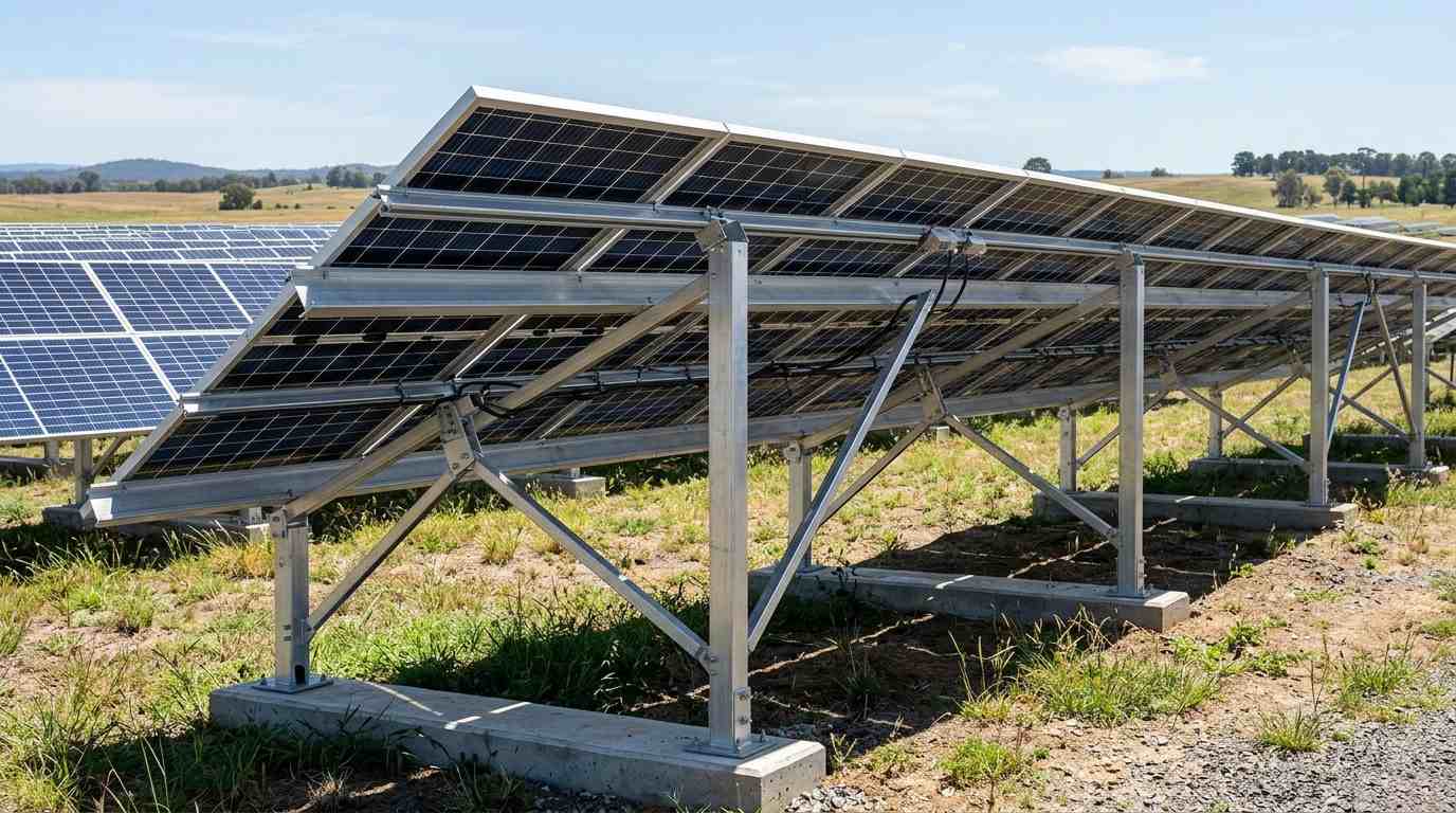
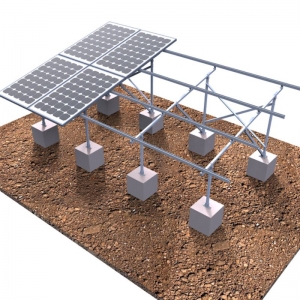
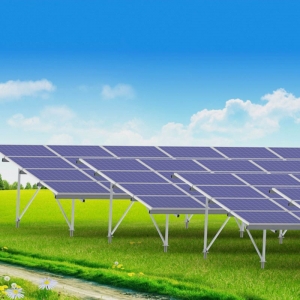
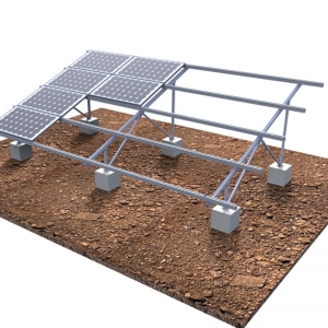
SunRack bifacial-optimized ground mounting system designed to eliminate rear-side shading
1. The Mechanics of Bifacial Gain and The "Albedo Effect"
To understand how to design the racking, we must first understand how rear-side generation works. The rear side of a bifacial panel does not receive direct sunlight; it relies entirely on Albedo. Albedo is a metric (ranging from 0 to 1) that measures how much solar irradiance is reflected by the ground surface beneath the array.
Different ground conditions reflect light differently. Dark asphalt absorbs light (low albedo), while fresh snow or white painted concrete reflects almost all of it (high albedo). Your mounting system must be designed to maximize the volume of this reflected light reaching the back of the panel.
| Ground Surface Type | Estimated Albedo Factor | Potential Bifacial Yield Gain |
|---|---|---|
| Fresh Snow | 0.80 - 0.90 | Up to 25% (Requires high ground clearance) |
| White TPO Membrane Roof | 0.60 - 0.70 | 15% - 20% |
| Light Concrete / Dry Sand | 0.30 - 0.40 | 8% - 12% |
| Grass / Vegetation | 0.15 - 0.25 | 5% - 8% |
| Dark Asphalt | 0.05 - 0.10 | Under 5% |
2. The Engineering Rule of Ground Clearance
The single most important structural variable for a bifacial array is Ground Clearance (the distance from the earth to the lowest edge of the tilted solar panel).
If the mounting structure holds the panels too close to the ground (e.g., 0.4 meters or lower), the panels will block the sunlight from hitting the ground directly beneath them, creating a massive "dark zone." With no light hitting the ground, there is no light to reflect back to the rear cells. Furthermore, low clearance traps heat, reducing the module's voltage efficiency.
For EPCs deploying high-clearance utility solar ground mounts, Sunforson engineers typically recommend a minimum ground clearance of 1.0 meter to 1.5 meters. Elevating the structure allows diffuse sunlight to reach deep underneath the array, illuminating a larger footprint of the ground and significantly boosting the albedo reflection factor. While this requires longer galvanized steel ramming piles (increasing upfront material CapEx slightly), the financial modeling consistently proves that the resulting 10%+ energy gain rapidly pays for the extra steel.
3. Eradicating Rear-Side Shading: The Purlin Problem
Even with perfect ground clearance and brilliant white snow, your bifacial yield can be crippled by the mounting frame itself. Traditional solar racking utilizes thick horizontal purlins (support rails) that run directly behind the center of the panels. In a monofacial setup, this doesn't matter. In a bifacial setup, these thick steel or aluminum rails cast a permanent, hard shadow across the rear-facing solar cells.
Because solar cells are wired in series, shading even a small portion of the rear side can bottleneck the electrical output of the entire string (the "garden hose" effect). To solve this critical flaw, Sunforson has re-engineered our structural geometry:
- Edge-Clamping & Repositioned Rails: Instead of running support rails directly behind the active cell area, our bifacial-optimized brackets position the longitudinal rails at the absolute extreme edges of the module frame, or utilize the panel's own frame structural strength to eliminate center rails entirely.
- Portrait Orientation Optimization: Whenever possible, mounting bifacial panels in a "Portrait" orientation (vertically) on a 2-in-portrait (2P) structural layout allows the racking supports to align parallel to the cell strings. If a shadow is cast, it only affects one bypass diode zone rather than knocking out the entire panel's production.
- Thinner, High-Tensile Profiles: By using ultra-high-tensile Q355B galvanized steel or AL6005-T5 aluminum, our engineers can reduce the physical width and cross-section of the support beams, shrinking their shadow footprint without sacrificing any wind or snow load capacity.
4. Application Scenarios: Roofs and Carports
While ground mounts are the most common application, bifacial technology is expanding rapidly into commercial and industrial (C&I) sectors. The structural rules, however, remain stringent.
Bifacial Panels on Commercial Flat Roofs
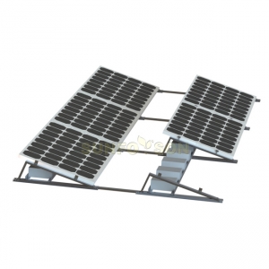
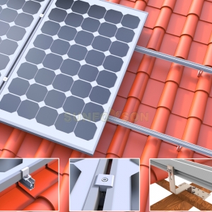
Standard flush-mount roof brackets (10° tilt, sitting inches from the roof) are virtually useless for bifacial panels. However, if a commercial building features a highly reflective white TPO membrane roof, EPCs can harvest massive yields by deploying a flat roof ballasted racking for bifacial panels. These specialized ballasted triangles are engineered to elevate the panels higher off the roof deck (often at 20° to 30° tilts) to create a wide "reflection corridor" beneath the array, allowing the white roof to bounce irradiance into the rear cells while protecting the waterproofing membrane.
The Ultimate Synergy: Bifacial Solar Carports
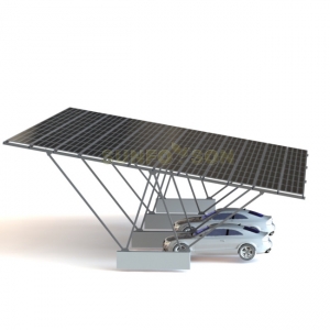
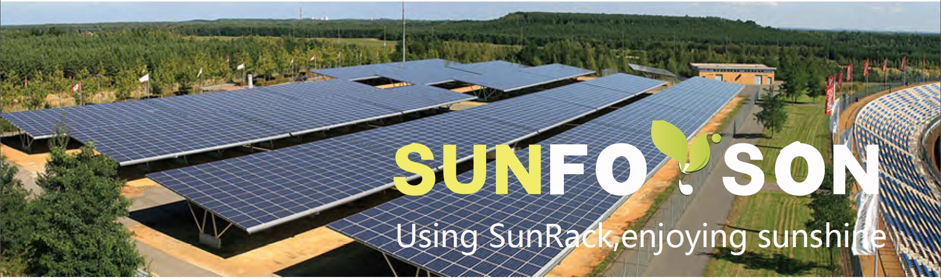
Perhaps the most perfect environment for bifacial modules is over a parking lot. A high-end bifacial commercial solar carport canopy inherently features massive ground clearance (typically 2.5 meters to 3.0 meters). The concrete parking surface below provides an excellent, constant albedo. Sunforson engineers our waterproof carport W-rails to sit flush between the panels, ensuring that the entire underside of the canopy is completely unobstructed, turning the parking lot into a 360-degree light harvesting engine.
Structural Checklist for Bifacial EPC Procurement
When sending your RFQ (Request for Quotation) to a Chinese solar mounting manufacturer, do not just ask for "ground brackets." Protect your LCOE by demanding the following in your structural design:
- Minimum Ground Clearance Guarantee: Ensure the structural drawing explicitly shows the lowest module edge at a minimum of 1.0m from grade.
- Shadow Footprint Analysis: Ask the engineering team to provide a CAD overlay demonstrating exactly where the purlins and rails will sit relative to the rear glass of your specific bifacial panel model.
- Row Spacing (Pitch) Optimization: Bifacial arrays require wider row spacing than monofacial arrays to prevent one row from casting shadows on the ground reflection area of the row behind it. Ensure the mounting supplier calculates this expanded pitch into their layout.
Frequently Asked Questions (FAQ) for Bifacial Engineering
Q1: Does a higher ground clearance reduce the wind resistance of the mounting system?
Raising the clearance does increase the leverage and aerodynamic uplift forces applied to the foundation. This is why you cannot simply use a standard bracket and "make the legs longer." Sunforson utilizes advanced FEA (Finite Element Analysis) to thicken the steel piles and deepen the ramming depth, ensuring the elevated bifacial structure safely withstands high wind loads (up to 60m/s).
Q2: Are trackers required to benefit from bifacial panels?
No. While single-axis trackers combined with bifacial panels offer the absolute highest yield in the industry, highly optimized Fixed-Tilt ground mounts with wide row spacing and high clearance can still deliver an incredibly strong ROI, with far lower maintenance costs and zero moving parts.
Q3: Is the extra cost of specialized bifacial racking worth it?
Absolutely. Purchasing premium bifacial panels but suffocating them with generic, low-clearance racking is a severe waste of capital. The slight increase in racking material cost (for taller posts and optimized rails) is mathematically insignificant compared to the 10% to 15% compounded energy revenue gained over the 25-year lifespan of the project.
Unlock the Full Power of Your Bifacial PV Project
Do not let poor structural engineering cast a shadow over your solar investment. Partner with the experts at Xiamen Sunforson Power Co., Ltd. Our dedicated R&D team provides highly customized, mathematically optimized racking solutions designed specifically to maximize albedo reflection and eliminate rear-side shading.
Send us your panel datasheet and site topography for a free bifacial structural analysis:
info@sunforson.com